Hi there,
New poster here. Got inspired by these two threads:
Laugh's Tutorial on how to modify a Paewang multi-format arcade stick
Cannon's thread, building on Laugh's, for modifying a Datel
I found both AFTER I had purchased a Datel Arcade Pro due to the multi-format potential. I was looking to see if I was the only one who thought it was crap. Of course, I wasn't. But I didn't want to buy a TE quite yet and felt like having a project and I've never done an electronics/DIY kind of thing before, so this felt like a good place to start.
Because I've got so much out of reading those threads, here's my way to give back something and share what I've learnt and had to work-out to make things easier for people.
Summary: Bought a Datel Arcade Pro joystick with multi-format PCB. Kept the PCB, the plastic case, through everything else away and replaced the buttons with OBSF-30s and the stock joystick with a Sanwa JLF-TP-8Y-SK.
In essence, I turned this crappy stock into an arcade quality stick that is easier to transport and works on anywhere!
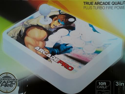
Anyway, this is what I started with:
![1.jpg]()
This is the case with all the parts stripped out. The buttons are the worst part by a long shot and the joystick is less than passable.
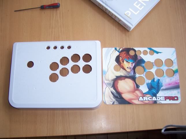
Be gentle and remove the artwork from the top. I used a small screwdriver underneath the corner and gently peeled it all off.
![2.jpg]()
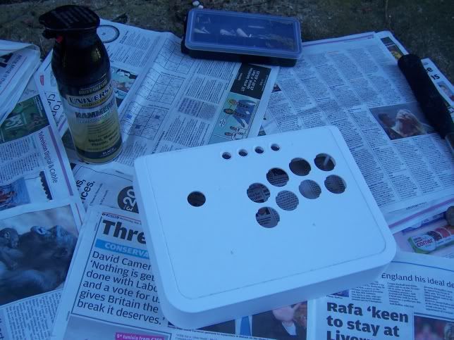
Your biggest problem here is how to get all that sticky crap off that's left after you've removed the artwork. Whilst I've seen people do it with washing up liquid and the like, the best thing to use is lighter fluid. This will dissolve all that sticky crap and, whilst you may need a reasonable amount, it will get everything off.
![3.jpg]()
See? Smooth as a baby's bottom.
Next job is to sort your artwork out. I'm a big fan of the game Bayonetta and thought that the anti-heroine herself would make a great subject for some arcade stick art. Anyway, wouldn't every man like to 'have Bayonetta on their stick'? (fnarr, fnarr! ;-) )
So I stuck the previously removed artwork to a piece of A4 paper and scanned it in and then played around with the image to make a template for the Datel Stick.
A word of warning about the following - I did my absolute best, but I would recommend that you expand the template slightly at the edges. This template is EXACT and therefore gives no room for error - something that's difficult to avoid when you're cutting up your own art!
Datel Arcade Pro Artwork Template
So, having scanned in the art and created the template, I got my artwork sorted and then I stuck it through a laminator. Now I've seen people use stores/services called lamilabel and such like, but I thought what's wrong with laminating it yourself?
![4.jpg]()
I would also strongly suggest at this point that you learn from my mistakes and DON'T do white circles where the buttons should be! Again, no room for error if you put in white circles. I ended up redoing my template so that I had faint grey circles where the buttons where just to guide my cutting.
Also, I used GIMP to do all the artwork, so don't feel under threat if you don't have Photoshop. It's also totally free and open-source :-)
If you're laminating yourself then make several copies on the printer and laminator because you're going to need them!
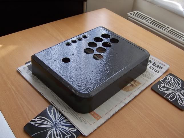
I chose in this instance to repaint the case a metallic black colour. Actually after the fact it looks more like a metallic very dark grey - not what I was looking for but pretty cool all the same. It's different and my case now kind of looks like it's make out of metal!
To prepare the plastic case for its respraying make sure that you sand it all down a bit beforehand. This ensures that the paint has a 'key' to stick onto and it helps ensure that there's no grease that will get in your way.
![5.jpg]()
![6.jpg]()
![7.jpg]()
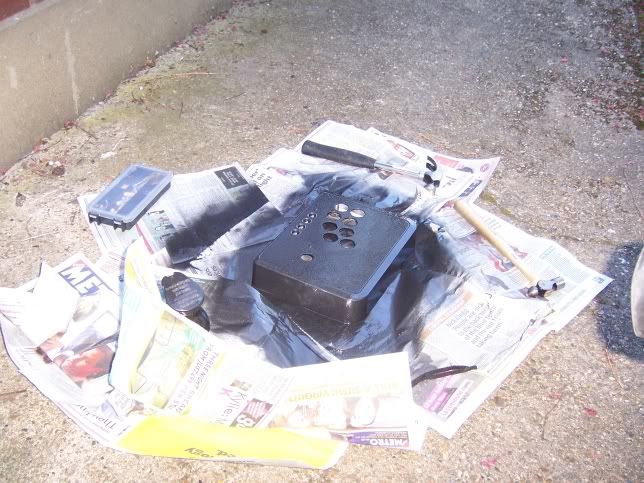
Remember that you may have to purchase a primer paint and colour paint for your case. In this case I used a 'Hammerite style' paint that didn't need preparation and would stick to anything.
Be outside when you do this unless you want to a) get high or b) get a headache or c) both!
Once the paint is dry (this may take a whole day - don't rush it! I did, and I've some imperfections in my paintwork to prove it!) you've got to widen the holes for the 'main' buttons to accept the OBSF-30s. You could use the smaller Crowns if you like as per Laugh's tutorial, but personally if you can get hold of a Dremel kit to sand out those holes to 30mm then it's no big deal. Even with sandpaper it'd be fine, it would just take longer. I did a combo of both because it CAN be difficult to make a big mistake with the dremel if you're not careful and have a steady hand.
Now, the artwork.
I'm not sure what the perfect route out is, but there's a problem with the turbo, back/select, guide/home, start buttons at the top, at least as far as custom artwork goes:
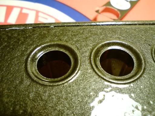
![8.jpg]()
You can see that the button edges are raised. It's not even a solution to sand them off because you've then got the recess inside which makes it difficult to cut. You can't sand off the 'inside-recessed' bit because it holds the buttons on the top row (which I also sprayed with the black hammerite styley paint). It's a MAJOR pain when trying to cut out the button holes.
When you're cutting out your laminated art then the edges are not so difficult and the 'main' buttons are easy because they're going to be covered by the lip of the OBSF-30s anyway and so there's a reasonable room for error. Not so with the top buttons. Any abberation looks well ugly. My solution was to not cut all 4 circles, but to cut straight along the top and just two curves at either end i.e. cut the whole panel out closely not each individual button (I hope that later pictures make this clear).
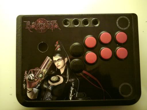
So, having got my artwork cut and mounted (and stuck down with PVA glue - cheap and available) and my buttons snapped in, my case looked like this:
![9.jpg]()
![10.jpg]()
At which point I started thinking, "Okay, this is going to be pretty cool actually and worth the effort!".
Now the wiring.
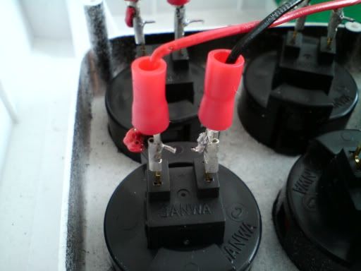
I started by wiring up the buttons first. I chose to solder all the wires to spade connectors to slip onto the edge of my button connections for three reasons:
a) It meant that I could do all my soldering outside the case and this would be easier
b) If, at any time, I wanted to rearrange the config of my buttons, I don't have to resolder, I just pull off and swap over connectors.
c) I can pull off the wires, snap out the buttons and replace the artwork if I ever felt like it.
It takes hardly any more time in soldering and only cost me another £3 or so from Maplins (I'm English BTW - it's a big electronics chain).
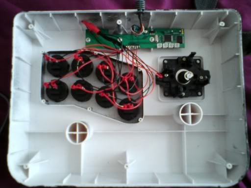
Here's the evidence:
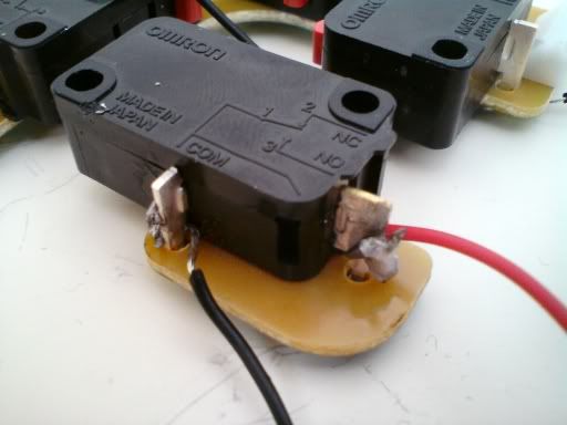
![11.jpg]()
![12.jpg]()
There are details about the soldering positions and how to wire up the earth in Laugh and Cannon's threads. With the earth I twisted and taped all the grounds to one wire and then soldered that to the PCB.
![13.jpg]()
For the joystick there are two ways you can go:
a) Solder directly to the microswitches themselves (this is the route if you don't have a harness as detailed below)
b) use a joystick harness to plug into the JLF and then solder those 5 wires to the motherboard.
You don't HAVE to have the custom harness for the JLF - after all, the original joystick has no PCB and so has all its microswitches connected directly.But it does make your life easier and save you a little soldering.
![14.jpg]()
However, please make note that in the above diagram (taken when I had soldered INCORRECTLY!) the wire attached to the '3' should be the live wire and the other one the ground.
If you plan on using the connectors from the stock joystick please note the following:
The red wire is the ground and the black wire is the live!
Maybe this isn't news to some of you, but I assumed that red was live and it would have saved me a load of time if I'd known otherwise!
I personally kept the connectors from the stock joystick, just cut the grounds and wrapped them together from 3 of the directions (there needs to be one ground if using the harness and therefore the PCB from the joystick) and left the ground from 1 microswitch connected to the JLF PCB. I then used the harness and connected each of the 5 wires to the appropriate connector by just twisting the wires together and wrapping in insulation tape.
![17.jpg]()
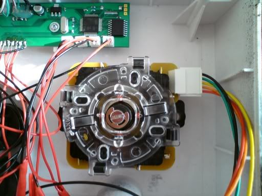
Now, an important word on an area of confusion for which wire does what coming out of the JLF harness and, subsequently, where do you solder the damn thing?
In the photo of the joystick base above, the pins/wires from top the bottom are:
Top - Ground
Right
Left
Up
Bottom -Down
So in my photo above:
Ground = Black
Right = Green
Left = Yellow
Up = Orange
Down = Red.
I left the ground on the UP direction connector on and twisted that with the black wire from the harness, but it doesn't really matter as long as you use one ground.
The wires on your harness will vary from mine. It's the order of the pins illustrated above WHEN IT'S MOUNTED IN THE CASE that's important. Colours are for illustration only.
Sorry if this seems long for some, but I got very confused at this point and had to look at the PCB on the JLF to work this out, as well as working it out from Laugh's photos!
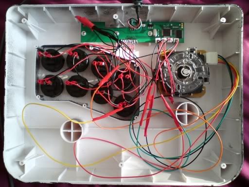
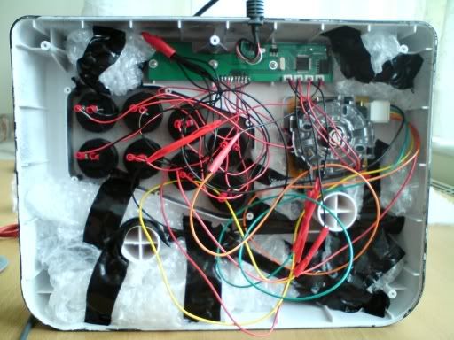
Finished wiring (see the 'twisted and insulated' wire, therefore saving you soldering and time!) inside the case:
![18.jpg]()
So after this I also wanted to add some weight and stability to it.
I did the cheap skate thing and went and got £1.50 worth of coppers (1ps and 2ps) and taped them into rolls and duck taped them into the case. I also then added some bubble wrap in amongst it. These two things add weight and make the case feel solid and sturdy rather than cheap, hollow and naaaaaasty like the original.
![19.jpg]()
Phew, got that out.
This was my first electronics/DIY project, nevermind my first arcade stick mod and I have to say that I don't think I did all that bad. It's working and plays lovely. It's wonderful to have arcade quality to play on (although my skills leave a little to be desired!). No plinking that some have complained about. Only thing to date that I haven't had opportunity to test is switching to PS3 mode (I have an XBox360).
So, I've gone from this...
![20.jpg]()
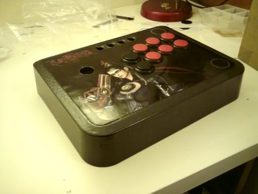
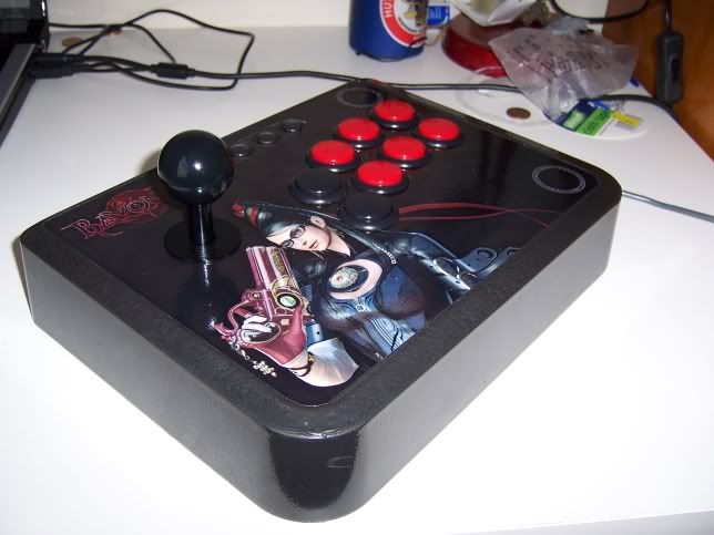
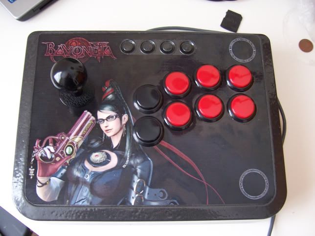
...to this...
![21.jpg]()
![22.jpg]()
I really hope I've helped out some people by putting this up. If you've any questions then let me know. The whole purpose of posting and spending the time doing all these pics was to add to the knowledge that inspired me. Because this has been so long, I may have left something out!
Peace out. Hope you like the stick!
thesynapse
New poster here. Got inspired by these two threads:
Laugh's Tutorial on how to modify a Paewang multi-format arcade stick
Cannon's thread, building on Laugh's, for modifying a Datel
I found both AFTER I had purchased a Datel Arcade Pro due to the multi-format potential. I was looking to see if I was the only one who thought it was crap. Of course, I wasn't. But I didn't want to buy a TE quite yet and felt like having a project and I've never done an electronics/DIY kind of thing before, so this felt like a good place to start.
Because I've got so much out of reading those threads, here's my way to give back something and share what I've learnt and had to work-out to make things easier for people.
Summary: Bought a Datel Arcade Pro joystick with multi-format PCB. Kept the PCB, the plastic case, through everything else away and replaced the buttons with OBSF-30s and the stock joystick with a Sanwa JLF-TP-8Y-SK.
In essence, I turned this crappy stock into an arcade quality stick that is easier to transport and works on anywhere!
Anyway, this is what I started with:
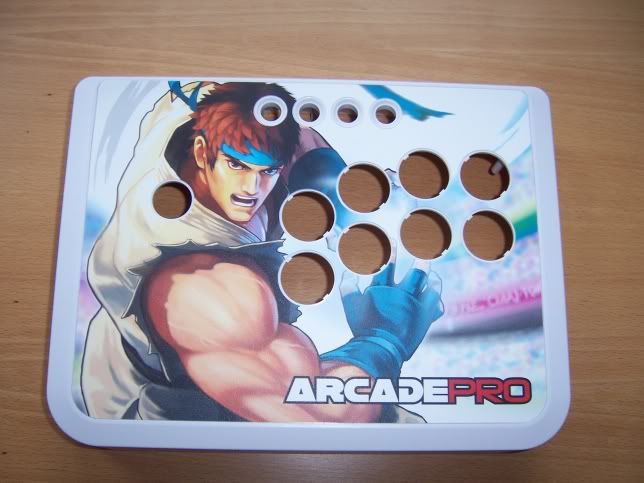
This is the case with all the parts stripped out. The buttons are the worst part by a long shot and the joystick is less than passable.
Be gentle and remove the artwork from the top. I used a small screwdriver underneath the corner and gently peeled it all off.
Your biggest problem here is how to get all that sticky crap off that's left after you've removed the artwork. Whilst I've seen people do it with washing up liquid and the like, the best thing to use is lighter fluid. This will dissolve all that sticky crap and, whilst you may need a reasonable amount, it will get everything off.
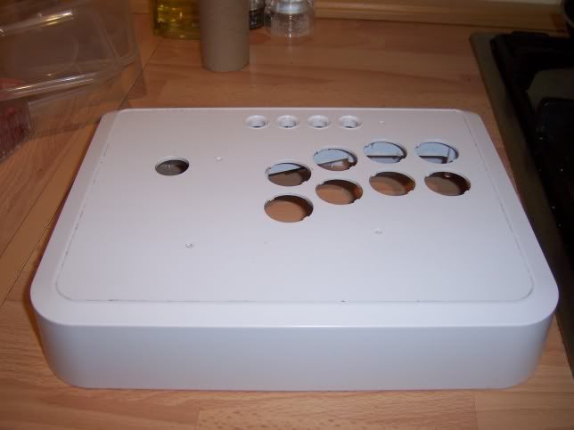
See? Smooth as a baby's bottom.
Next job is to sort your artwork out. I'm a big fan of the game Bayonetta and thought that the anti-heroine herself would make a great subject for some arcade stick art. Anyway, wouldn't every man like to 'have Bayonetta on their stick'? (fnarr, fnarr! ;-) )
So I stuck the previously removed artwork to a piece of A4 paper and scanned it in and then played around with the image to make a template for the Datel Stick.
A word of warning about the following - I did my absolute best, but I would recommend that you expand the template slightly at the edges. This template is EXACT and therefore gives no room for error - something that's difficult to avoid when you're cutting up your own art!
Datel Arcade Pro Artwork Template
So, having scanned in the art and created the template, I got my artwork sorted and then I stuck it through a laminator. Now I've seen people use stores/services called lamilabel and such like, but I thought what's wrong with laminating it yourself?
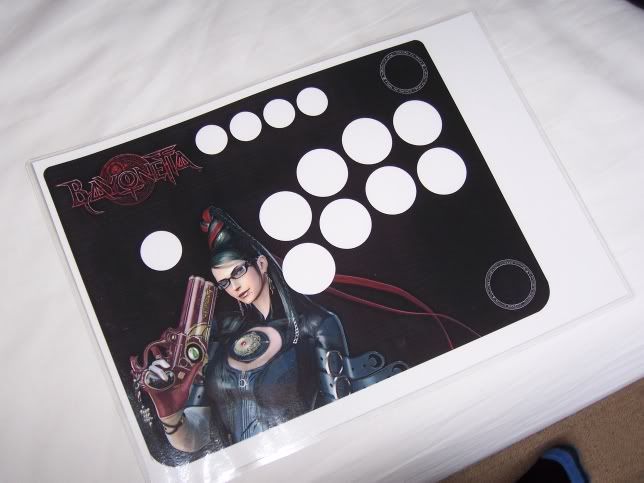
I would also strongly suggest at this point that you learn from my mistakes and DON'T do white circles where the buttons should be! Again, no room for error if you put in white circles. I ended up redoing my template so that I had faint grey circles where the buttons where just to guide my cutting.
Also, I used GIMP to do all the artwork, so don't feel under threat if you don't have Photoshop. It's also totally free and open-source :-)
If you're laminating yourself then make several copies on the printer and laminator because you're going to need them!
I chose in this instance to repaint the case a metallic black colour. Actually after the fact it looks more like a metallic very dark grey - not what I was looking for but pretty cool all the same. It's different and my case now kind of looks like it's make out of metal!
To prepare the plastic case for its respraying make sure that you sand it all down a bit beforehand. This ensures that the paint has a 'key' to stick onto and it helps ensure that there's no grease that will get in your way.
Remember that you may have to purchase a primer paint and colour paint for your case. In this case I used a 'Hammerite style' paint that didn't need preparation and would stick to anything.
Be outside when you do this unless you want to a) get high or b) get a headache or c) both!
Once the paint is dry (this may take a whole day - don't rush it! I did, and I've some imperfections in my paintwork to prove it!) you've got to widen the holes for the 'main' buttons to accept the OBSF-30s. You could use the smaller Crowns if you like as per Laugh's tutorial, but personally if you can get hold of a Dremel kit to sand out those holes to 30mm then it's no big deal. Even with sandpaper it'd be fine, it would just take longer. I did a combo of both because it CAN be difficult to make a big mistake with the dremel if you're not careful and have a steady hand.
Now, the artwork.
I'm not sure what the perfect route out is, but there's a problem with the turbo, back/select, guide/home, start buttons at the top, at least as far as custom artwork goes:
You can see that the button edges are raised. It's not even a solution to sand them off because you've then got the recess inside which makes it difficult to cut. You can't sand off the 'inside-recessed' bit because it holds the buttons on the top row (which I also sprayed with the black hammerite styley paint). It's a MAJOR pain when trying to cut out the button holes.
When you're cutting out your laminated art then the edges are not so difficult and the 'main' buttons are easy because they're going to be covered by the lip of the OBSF-30s anyway and so there's a reasonable room for error. Not so with the top buttons. Any abberation looks well ugly. My solution was to not cut all 4 circles, but to cut straight along the top and just two curves at either end i.e. cut the whole panel out closely not each individual button (I hope that later pictures make this clear).
So, having got my artwork cut and mounted (and stuck down with PVA glue - cheap and available) and my buttons snapped in, my case looked like this:
At which point I started thinking, "Okay, this is going to be pretty cool actually and worth the effort!".
Now the wiring.
I started by wiring up the buttons first. I chose to solder all the wires to spade connectors to slip onto the edge of my button connections for three reasons:
a) It meant that I could do all my soldering outside the case and this would be easier
b) If, at any time, I wanted to rearrange the config of my buttons, I don't have to resolder, I just pull off and swap over connectors.
c) I can pull off the wires, snap out the buttons and replace the artwork if I ever felt like it.
It takes hardly any more time in soldering and only cost me another £3 or so from Maplins (I'm English BTW - it's a big electronics chain).
Here's the evidence:
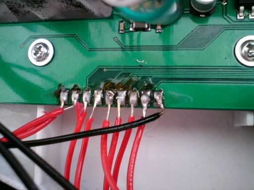
There are details about the soldering positions and how to wire up the earth in Laugh and Cannon's threads. With the earth I twisted and taped all the grounds to one wire and then soldered that to the PCB.
For the joystick there are two ways you can go:
a) Solder directly to the microswitches themselves (this is the route if you don't have a harness as detailed below)
b) use a joystick harness to plug into the JLF and then solder those 5 wires to the motherboard.
You don't HAVE to have the custom harness for the JLF - after all, the original joystick has no PCB and so has all its microswitches connected directly.But it does make your life easier and save you a little soldering.
However, please make note that in the above diagram (taken when I had soldered INCORRECTLY!) the wire attached to the '3' should be the live wire and the other one the ground.
If you plan on using the connectors from the stock joystick please note the following:
The red wire is the ground and the black wire is the live!
Maybe this isn't news to some of you, but I assumed that red was live and it would have saved me a load of time if I'd known otherwise!
I personally kept the connectors from the stock joystick, just cut the grounds and wrapped them together from 3 of the directions (there needs to be one ground if using the harness and therefore the PCB from the joystick) and left the ground from 1 microswitch connected to the JLF PCB. I then used the harness and connected each of the 5 wires to the appropriate connector by just twisting the wires together and wrapping in insulation tape.
Now, an important word on an area of confusion for which wire does what coming out of the JLF harness and, subsequently, where do you solder the damn thing?
In the photo of the joystick base above, the pins/wires from top the bottom are:
Top - Ground
Right
Left
Up
Bottom -Down
So in my photo above:
Ground = Black
Right = Green
Left = Yellow
Up = Orange
Down = Red.
I left the ground on the UP direction connector on and twisted that with the black wire from the harness, but it doesn't really matter as long as you use one ground.
The wires on your harness will vary from mine. It's the order of the pins illustrated above WHEN IT'S MOUNTED IN THE CASE that's important. Colours are for illustration only.
Sorry if this seems long for some, but I got very confused at this point and had to look at the PCB on the JLF to work this out, as well as working it out from Laugh's photos!
Finished wiring (see the 'twisted and insulated' wire, therefore saving you soldering and time!) inside the case:
So after this I also wanted to add some weight and stability to it.
I did the cheap skate thing and went and got £1.50 worth of coppers (1ps and 2ps) and taped them into rolls and duck taped them into the case. I also then added some bubble wrap in amongst it. These two things add weight and make the case feel solid and sturdy rather than cheap, hollow and naaaaaasty like the original.
Phew, got that out.
This was my first electronics/DIY project, nevermind my first arcade stick mod and I have to say that I don't think I did all that bad. It's working and plays lovely. It's wonderful to have arcade quality to play on (although my skills leave a little to be desired!). No plinking that some have complained about. Only thing to date that I haven't had opportunity to test is switching to PS3 mode (I have an XBox360).
So, I've gone from this...
...to this...
I really hope I've helped out some people by putting this up. If you've any questions then let me know. The whole purpose of posting and spending the time doing all these pics was to add to the knowledge that inspired me. Because this has been so long, I may have left something out!
Peace out. Hope you like the stick!
thesynapse